

An electronic stethoscope is an easy and fun listening device to make. It only requires some basic knowledge of electronics, and can be built with some basic easy to find parts. I have been having a great time using it to crack saf... I mean listen to my heartbeat. Yes! I have been having a great time listening to my inner workings.
Step 1: Go get stuff

You will need:
- 1-1/2" flat round cabinet knob
- LM386 Low Voltage Audio Power Amplifier (Model: LM386 | Catalog #: 276-1731)
- MPF102 Transistors (Model: MPF102 FET | Catalog #: 276-2062)
- 1K Ohm 1/4-Watt Carbon Film Resistor (Model: 271-1321 | Catalog #: 271-1321)
- 1M Ohm 1/4-Watt Carbon Film Resistor (Model: 271-1356 | Catalog #: 271-1356)
- 10 ohm 1/4W 5% Carbon Film Resistor (Model: 271-1301 | Catalog #: 271-1301)
- 4.7K Ohm 1/4-Watt Carbon Film Resistor (Model: 271-1330 | Catalog #: 271-1330)
- (x2) 0.047µF 50V 10% PC-Mount Capacitor (Model: 272-1068 | Catalog #: 272-1068)
- 220µF 35V 20% Radial-lead Electrolytic Capacitor (Model: 272-1029 | Catalog #: 272-1029)
- 100µF 35V 20% Radial-lead Electrolytic Capacitor (Model: 272-1028 | Catalog #: 272-1028)
- 0.1µF 50V Hi-Q Ceramic Disc Capacitor (Model: 272-135 | Catalog #: 272-135)
- Project Enclosure (3x2x1") (Model: 270-1801 | Catalog #: 270-1801)
- Multipurpose PC Board with 417 Holes (Model: 276-150 | Catalog #: 276-150)
- JVC® Gumy Earbuds (Model: HAF150B | Catalog #: 55042619)
- 10K-Ohm Linear-Taper Potentiometer (Model: 271-1715 | Catalog #: 271-1715)
- Hexagonal Control Knob (Model: 274-407 | Catalog #: 274-407)
- 1/8" Mono Panel-Mount Audio Jack (Model: 274-251 | Catalog #: 274-251)
- 6-Ft. Mono 1/8" Plug to Mono 1/8" Jack with Shielded Cable (Model: 42-2472 | Catalog #: 42-2472)
- Fully Insulated 9V Battery Snap Connectors (Model: 270-325 | Catalog #: 270-325)
- Enercell® Alkaline 9 Volt Battery (Model: 23-853 | Catalog #: 23-853)
- 90dB Piezo Pulse (Model: 273-066 | Catalog #: 273-066)Step 2: Cut

Using a sharp pair of scissors, trim your circuit board lengthwise so that only the center pads are left.

Note: You may want to use a dust mask while doing this, as circuit board dust is bad for you when inhaled. Cutting the board with scissors, greatly reduces, but does eliminate dust.
Step 3: Build

Build the circuit tightly and as close to one side of the board as possible.

For now, don't worry about including the power switch, audio jack, potentiometer or piezo. These will be handled later.
Step 4: Trim

Once the bulk of your circuit has been built. Trim the board as small as possible in such a way that it won't interfere with the circuit itself, and remember to leave a few solder pads for the parts that you still need to connect.

Step 5: Mark and drill
Flip your case on its side. Make two _ _ _ marks _ _ _

Drill these marks using a 1/4" drill bit.
Step 6: Mark and drill again

On the two smallest sides of the case make centered marks.
Drill an 3/16" hole on the side closest to the other holes that you have just made.
Drill a 1/4" hole where the mark is on the opposite side of the case.
Step 7: Wires
With the potentiometer knob facing towards you, solder a black wire to the left potentiometer pin.

Solder red wire to the other two pins.
Step 8: More wires
Solder a red wire to the center toggle switch pin.

Solder the red wire from the 9V battery clip to either of the other pins.
Step 9: Some more wires
Attach a single red wire to the two pins on the bottom of the audio jack.

Attach a black wire to the ground pin on the side.
Step 10: Install
Install the potentiometer and toggle switch right next to each other inside the case.

Install the audio jack into the 1/4" hole on the opposite end of the case.
Step 11: Drill


Drill and 1/8" hole near the edge of the cabinet handle.

Step 12: Mount
For our purposes, the flat side of the cabinet handle will be considered the front.


Pass the red and black wires of the piezo through the hole you just drilled from front to back.

Epoxy the piezo to the cabinet handle such that the flat side of the piezo is facing out.
Be careful to leave a tiny bit of space between the cabinet handle and the solder points on the piezo (just in case the handle is conductive).
Step 13: Trim
Take your audio cable and cut a 3 foot section of cable out of it.
Don't worry about preserving the ends. We just need the shielded cable.
Step 14: Expose

Peel back the cable and twist together the shielding to form one single wire and expose the signal wire to form another.
Step 15: Attach
Solder the red wire from the piezo to the signal wire of the cable.

Solder the black wire to the cable's shielding.
Epoxy it all to the back of the cabinet handle in such a way that the solder joints won't make contact with either each other or the handle itself.
Step 16: Passing through
Pass the other end of the audio cable through the remaining hole in the case.
Tie a single knot to prevent it from passing back through.
Strip back the cable and separate the wires as you did in Step 14.
Step 17: Solder it all up
Complete the circuit as specified in the schematic.

Note that the audio cable's shielding goes to ground and that the center pin from the toggle switch goes to +9V.
The power switch goes between the red wire on the battery connector and the +9V in connection on the circuit board.
Step 18: Power
Plug in your 9V battery and install it inside the case.

If all has been done right, it should fit snugly.
Step 19: Case closed
Put the lid on the case and screw it shut.
Step 20: Knob

Attach your knob to the potentiometer.
Step 21:
Plug in your ear buds or headphones.
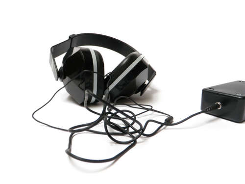
I used a pair of headphones and ear protection to make passive noise canceling headphones (jackhammer headphones).


Hi, do you have results for this project. I am trying to do this project as my school project can you help me about it
ReplyDelete